I made a short video where I attempt to cover antenna theory basics or as I call it "black Magic".
|
I finally decided to expand out of the VHF/UHF bands into HF. I wanted an "invisible" antenna, so I'm starting with an attic mounted G5RV antenna. The junior version from MFJ that covers 40 meters through 10 meters on the ham bands. 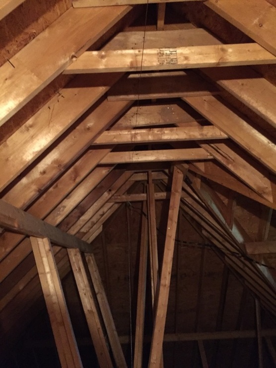 Antenna mounted as high as practical. You can see it's clear of metal objects and the ladder line goes off to the right at a 90 degree angle. Not ideal, but I'm avoiding routing it near any air ducts and wiring in the attic. 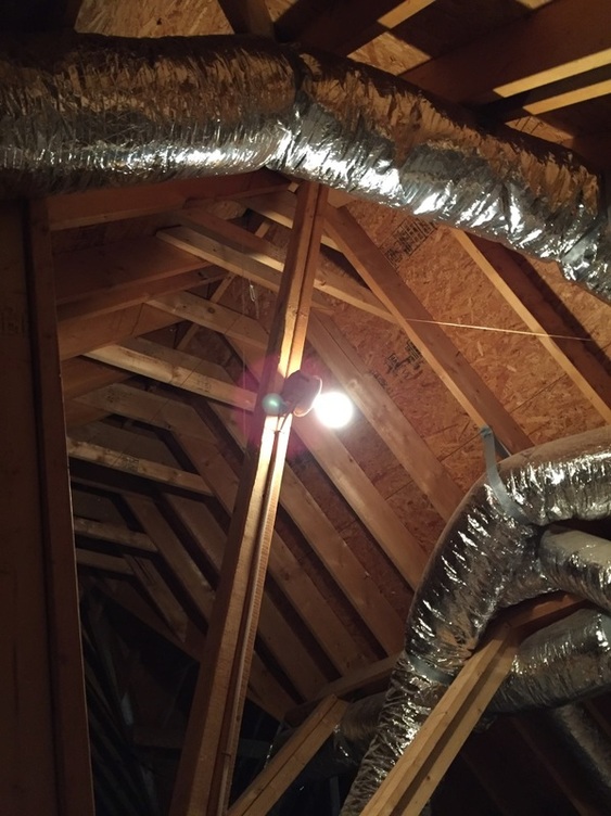 Since I have a hip roof, the radials are bent down. The supports are wire tie loops supported with nylon twine. This radial gets the closest to metal. The foil on the ducts may cause the antenna to have a null or contribute to an unwanted noise gain. 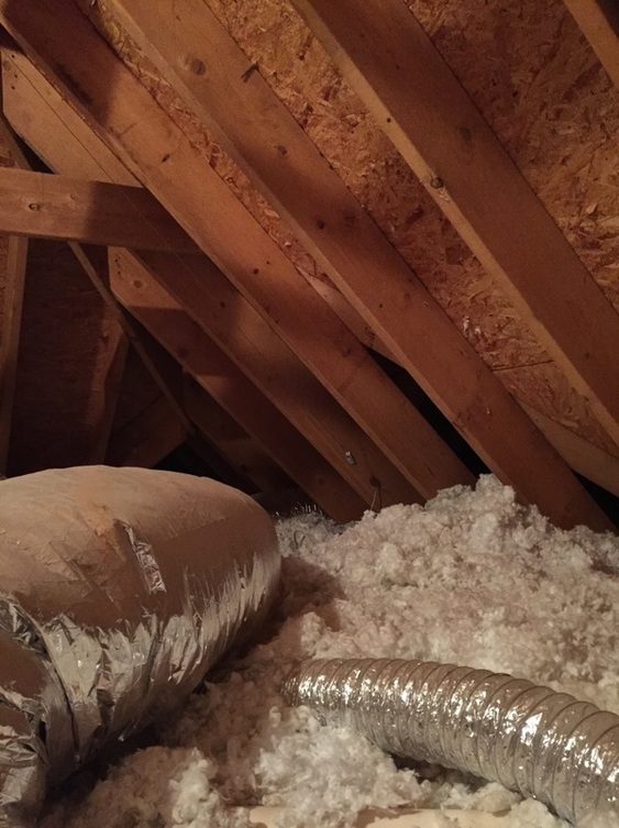 You can see the end insulator, again supported with twine. And the duct work I'm trying to avoid. 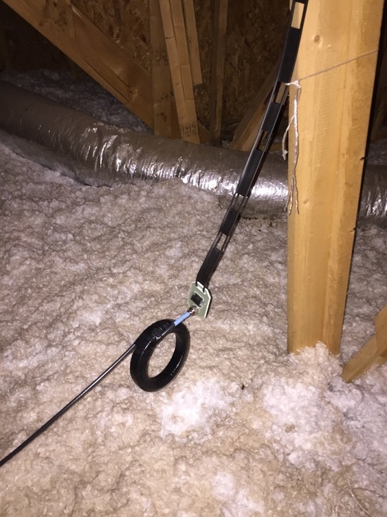 Here is the ladder line to coax transition. This was my first time installing a UHF connector on coax. It turned out neat with the blue heat shrink. Also, since this is a balanced multi-band antenna (not usually reasonant), MFJ recommended constructing a balun by looping the coax. This is 10 loops around 5" in diameter. The function of the loops is to provide high impedance to any common mode current. Ideally, in a balanced antenna, balanced feed line, all of the current would be differential mode. That is the current on the coax shield would be equal and in opposite direction from the current on the center conductor. If that's the case, the loops will not add impedance to the current and all the energy is radiated by the antenna. However, any current on the shield in addition to the differential mode current would see the inductance of the loops. That inductance helps to prevent and minimize common mode currents. You don't want common mode currents because they add to the noise of reception and can cause problems during transmission. This is because the common mode currents cause the coax to act as an antenna, and some of the energy is radiated by the coax shield instead of the antenna.
We'll see how it works when we get everything hooked up on the radio end. I'm embarking on a journey 95,000 feet into the air, a short voyage into near space. But I'm not really going. A camera, GPS receiver, radio, and some specialized electronics are hitching a ride on a weather balloon. I'm getting a start in high altitude ballooning, a recent "nerd" hobby. One of the parts is the radio. You need a radio so you can track and recover the balloon. What fun is it send a camera nearly to space unless you can get pictures off of it, right? A solution is to use APRS, which is a system built by HAM radio operators to exchange digital information including GPS coordinates. In fact, several websites tie into the system to provide you with maps and help you track objects reporting their GPS coordinates. To use APRS, you need a HAM radio license. To get the license you have to pass an exam. Tonight, I attended my first Tri County Amateur Radio Club meeting. I walked up, introduced myself, and mentioned that I was interested in getting my license and had been studying. The gentleman I was talking to said, you want to test tonight? I said, why not? And he called out to Roger, who was getting two other people ready for their exams. I sat down, listened to the instructions, paid $10, and took the test by moonlight (we were outside and the sun was setting). And, I passed the exam!!! My thanks to Roger, the VE (Volunteer Examiner), and to the Tri County Amateur Radio Club for their help and friendly welcome! Jonathan Weaver (KM4FIK) APRS Websites: http://www.aprs.org/ http://www.findu.com/ http://www.openaprs.net/ http://aprs.fi/ 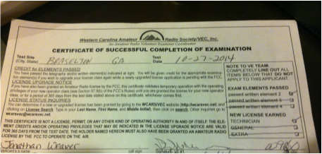 |
AuthorHusband. Father. Electrical Engineer. Electronics and woodworking hobbyist. Archives
December 2023
Categories
All
|
 RSS Feed
