Building the PPMScope
Some people have asked me if I have a working prototype of the PPMScope. The answer is yes. I have developed most of the software using a software "simulated" scope. However, I verified the software using a PPMScope laid out on a prototype board. I currently use a prototype that I constructed on punch board using a point to point wiring method. To help me route the wires on the punch board I have drawn a PCB, discussed below. 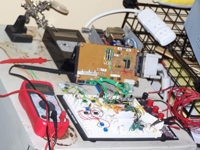
Prototype board prototype of PPMScope
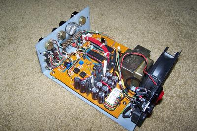
Punch board and point to point wiring prototype of PPMScope
Schematic
The schematic of the oscilloscope is drawn in Tiny CAD, a freely available electronic schematic software program. The schematics are installed in a clearly marked directory. I also have the schematic available as a PDF file, which you can access by clicking on the link below:
I have added a USB to serial port adapter for connecting the oscilloscope to the computer via a USB port using the UART of the microcontroller. The schematic for the adapter is below:
PCB
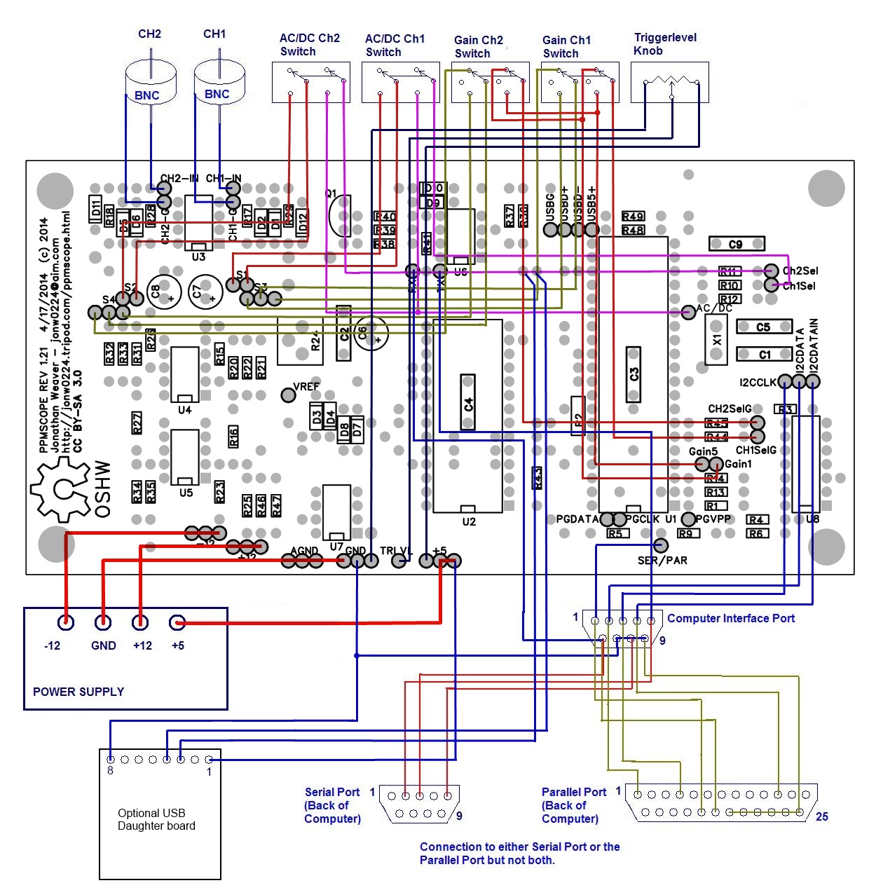
The PCB is drawn in FreePCB. I've also generated Gerber and PDF files for use in creating your own PCB's. A word of caution if you use the PDF files to make templates for etching: print them at actual size. Some versions of Adobe Reader attempt to scale the PDF to fit within the margins. Make sure you print them at actual size. To make the process of creating PCB's easier, the design of the PCB was created so that a single sided PCB could be used with jumper wires (you will notice the traces are simply single wires on the top side of the PCB. The layouts are linked below:
Many people have asked me about how to hook up components to the PCB. To answer those questions, I've included a diagram to show how components are wired to the PCB.
Also, here are the PCB layout files for the USB to Serial Daughter board Adapter:
Front Panel
There are only two BNC connectors, 4 toggle switches, and a knob to be mounted on the front panel. On the back panel, you could get by with a 9 pin D sub connector, a power cord, and an on switch. You may also want to add a power indicator LED. Below is a picture of what I built. The PPMScope in the picture is also a power supply and will also be a simple function generator. Kind of an "all-in-one" instrument. The blue area is the oscilloscope front panel. 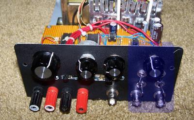
Parts List and Cost to build
To buy everything new (including building a 50 Watt power supply, a fan, the enclosure, etc) I estimate the cost to build at $115 US. However, the costs of many of these components can be improved upon by using scavenged parts or eliminating unnecessary parts. I estimate the oscilloscope could be built for $50 or less depending. The table below is an all inclusive parts list:
|
PPMScope
Projects | ||||||||||||||||||||||||||||||||||||||||||||||||||||||||||||||||||||||||||||||||||||||||||||||||||||||||||||||||||||||||||||||||||||||||||||||||||||||||||||||||||||||||||||||||||||||||||||||||||||||||||||||||||||||||||||||||||||||||||||||||||||||||||||||||||||||||||||||||||||||||||||||||||||||||||||||||||||||||||||||||||||||||||||||||||||

|
Content on this site is licensed under a Creative Commons Attribution 4.0 License.
I hope the information here is useful to those that find it. Page last update 2014 Aug 12. |
